Home

Profeti ordningen bryllup buck converter rl load byld salat Stipendium

The Difference between CCM and DCM Explained | Article | MPS

Four level three cell DC/DC converter connected to an R-L load. u k =... |  Download Scientific Diagram
Four level three cell DC/DC converter connected to an R-L load. u k =... | Download Scientific Diagram

Circuit schematics of buck converter with a resistive load. | Download  Scientific Diagram
Circuit schematics of buck converter with a resistive load. | Download Scientific Diagram

Buck converter - Wikipedia

Buck Converters; Testing with Variable Duty Ratio and Switching |  Electrical Engineering | JoVE
Buck Converters; Testing with Variable Duty Ratio and Switching | Electrical Engineering | JoVE

circuit analysis - Is current waveform of given dc-dc converter correct? -  Electrical Engineering Stack Exchange
circuit analysis - Is current waveform of given dc-dc converter correct? - Electrical Engineering Stack Exchange

Discontinuous Conduction Mode of Simple Converters - Technical Articles

Buck converter - Wikipedia

Auxiliary current control for improving unloading transient recovery of buck  converter | SpringerLink
Auxiliary current control for improving unloading transient recovery of buck converter | SpringerLink
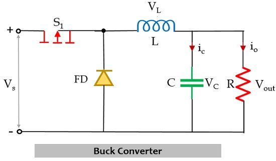
SMPS Basics - The Buck Converter

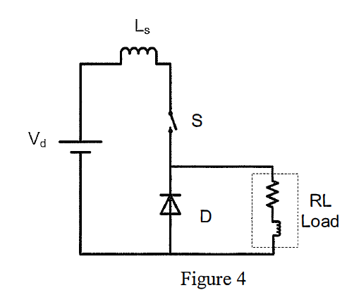
Solved Figure 4 shows the circuit diagram of a buck dc-dc | Chegg.com

Solved Consider the buck converter shown below. The input | Chegg.com

What is Buck Converter? Operating Principle and Waveform Representation of Buck  Converter - Electronics Coach
What is Buck Converter? Operating Principle and Waveform Representation of Buck Converter - Electronics Coach

Adaptive fuzzy logic controller for DC–DC converters - ScienceDirect

Low Noise Passive Filter Design for Buck Regulators

A basic two-cell DC-DC buck converter with an RL load and its control... |  Download Scientific Diagram
A basic two-cell DC-DC buck converter with an RL load and its control... | Download Scientific Diagram

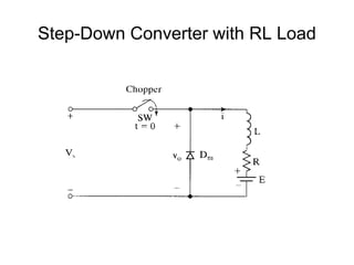
Unit- 3 DC-DC Converter

Solved] A buck converter, as shown in Figure (a) below, is working i

filter - Buck Converter with RLE Load - Electrical Engineering Stack  Exchange
filter - Buck Converter with RLE Load - Electrical Engineering Stack Exchange

Resources | Powersim, Inc

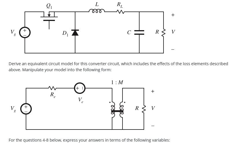
Solved 4. Question 4 Nonideal buck converter I​n the | Chegg.com

Buck–boost converter - Wikipedia

Four level buck converter circuit with R-L load | Download Scientific  Diagram
Four level buck converter circuit with R-L load | Download Scientific Diagram

Buck converter with R load and DC machine. | Download Scientific Diagram

filter - Buck Converter with RLE Load - Electrical Engineering Stack  Exchange
filter - Buck Converter with RLE Load - Electrical Engineering Stack Exchange

Buck-Boost converter for R and R-L loads using MATLAB - File Exchange -  MATLAB Central
Buck-Boost converter for R and R-L loads using MATLAB - File Exchange - MATLAB Central

A basic two-cell DC-DC buck converter with an RL load and its control... |  Download Scientific Diagram
A basic two-cell DC-DC buck converter with an RL load and its control... | Download Scientific Diagram

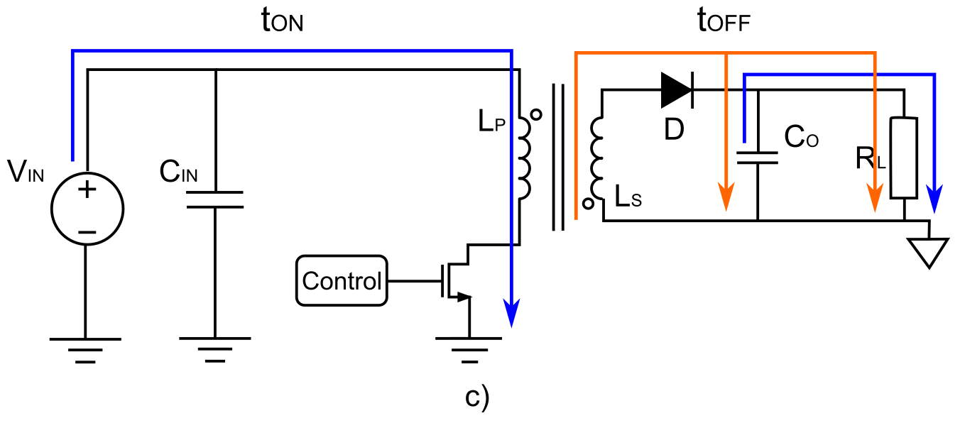
Shows the circuit diagram of a single-phase half-controlled bridge rectifier  with an RL load: Power Electronics Systems Report, NTU, Singapore
Shows the circuit diagram of a single-phase half-controlled bridge rectifier with an RL load: Power Electronics Systems Report, NTU, Singapore